Sheraton Suites Plantation
Sheraton Suites Plantation, a South Florida landmark, selected AirRevive to refurbish its 264 IEC guest room vertical fan coil units during its multi-million dollar renovation. The units were manufactured in 1989.
Sheraton Suites Plantation, a South Florida landmark, selected AirRevive to refurbish its 264 IEC guest room vertical fan coil units during its multi-million dollar renovation. The units were manufactured in 1989.
Fan Coil Units Manufacturer: IEC
Models#: TURBO4D5, TURBO6D5
Project Scope of Work: Guest room vertical fan coil unit refurbishment and valve replacement.
Challenge: The airflow was below design specifications due to impacted coils. The control valves were leaking by which was causing simultaneous heating and cooling, thus wasting energy and inhibiting the unit’s ability to cool and heat as designed. Coil condition was negatively impacting indoor air quality because organic material and dirt were stuck in the coil core. Airflow on high fan was insufficient for proper cooling. Insulation was torn and with fiber floating around return and supply areas. Fiber was stuck in coils. Electric heaters were dusty and dirty inhibiting proper heating and causing a foul smell. The motor was dirty and stuck to the blower wheel in some units. The blower assembly and wheel were dirty. The pans were rusting and corroding causing the drain line to clog. The project’s goal was to bring the units back to efficient operation.
Solutions: The refurbishment solution included:
Results
Before & After Airflow Data
The graph below displays before and after airflow on high fan setting. The red line from left to right demonstrates the airflow before service from low to high ranged from 210 FPM to 1010 FPM. The blue line demonstrates the airflow after service within the manufacturer’s design target of 810 FPM to 990 FPM. The horizontal axis represents the room numbers.

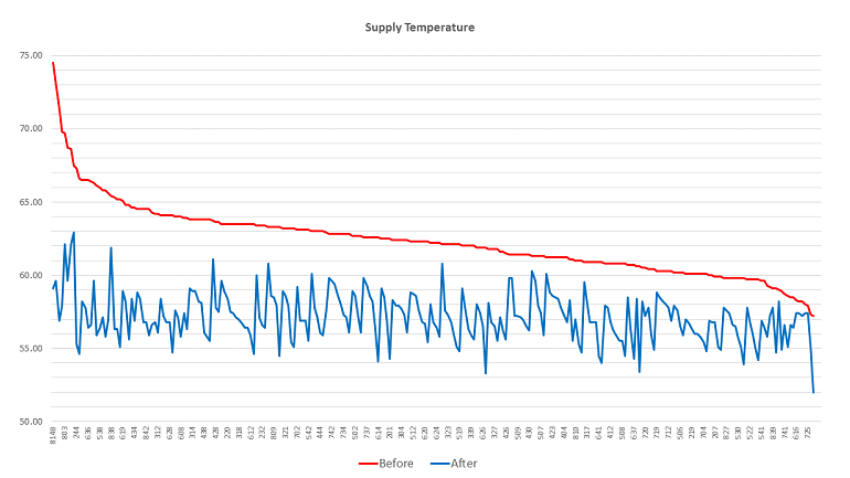
Before & After Supply Temperature Data
The graph below displays before and after supply temperature. The red line from left to right demonstrates the supply temperature before service from high to low ranged from 74 degrees to 57 degrees averaging 62.3 degrees. The blue line demonstrates the supply temperature after service averages 57.1 degrees. The horizontal axis represents the room numbers.