CUSTOMER: Full Service Hilton
LOCATION: Las Vegas, NV
INDUSTRY: Hospitality
AIRREVIVE SERVICE: Fan coil unit refurbishment and re-commissioning
FAN COIL UNITS: Williams ER04WES306D154
CUSTOMER: Full Service Hilton
LOCATION: Las Vegas, NV
INDUSTRY: Hospitality
AIRREVIVE SERVICE: Fan coil unit refurbishment and re-commissioning
FAN COIL UNITS: Williams ER04WES306D154
WHAT THE CLIENT NEEDED:
This stunning non-gaming all suite resort offers business and leisure travelers a serene getaway in close proximity to the strip. Accommodations include 418 guest rooms from studio to two bedrooms.
Hilton engaged AirRevive when they were looking to replace their 726 (Williams ER04WES306D154, 2 pipe system) guest room fan coil units. The units were found to be overblowing the manufacturer’s design curve by 50%. This resulted in inefficient heating and cooling.
It was clear the seventeen year old units kept up well. AirRevive recommended the coil be rejuvenated, the cabinet be refurbished and the EC motor retrofitted to restore the units to manufacturer’s design specifications – noting AirRevive coil rejuvenation is the best practice for retrofitting EC motors.
This report can be described as the Phoenix rising for full service hotel guest room fan coil units; just when hotel management thought they were in ashes, AirRevive brought them back to life with better power and efficiency than when they were new.
PROJECT CHALLENGES
AIRFLOW CHALLENGES
COIL TEMPERATURE CHALLENGES:
PROJECT GOALS:
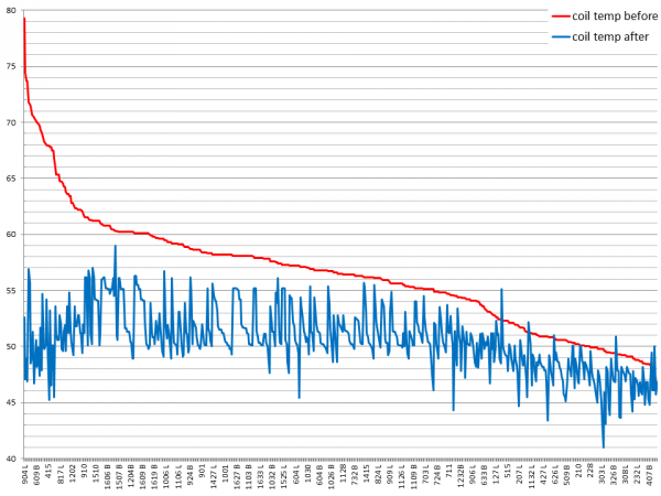
Coil Temperature Before and After Service
Summary: The site inspection determined the units had chronic over-blowing and difficulty reaching temperature set points. It also found many control valves were not working as designed causing simultaneous heating and cooling. The first step was to replace valves and to rejuvenate the coil.
The red line in the graph below depicts cooling coil temperature from high to low averaging 56 degrees before coil rejuvenation and valve replacement. 90% of the unit’s coil temperature was above 50 degrees before service. 73% of the unit’s coil temperature was above 53 degrees. 20% of the unit’s coil temperature was above 60 degrees.
The blue line demonstrates that after the coil rejuvenation and valve replacement coil temperature ranged from 57°F to 43°F after service. This resulted in an average coil temperature drop of 11% or 5.8 °F from 56 to 50 °F.
Airflow Before and After Service
Summary
Living room unit’s airflow was reset back to the manufacturer’s specification with an average of 600 CFM on high setting. The coil rejuvenation resulted in the coil and fins cooling the air more efficiently. Now that coils had unrestricted airflow and were working uniformly, each unit’s fan motor was retrofit with an EC motor. Note: Fan coil units located in the living rooms require more airflow (600 CFM on high setting) than studio or bedroom units (550 CFM on high setting).
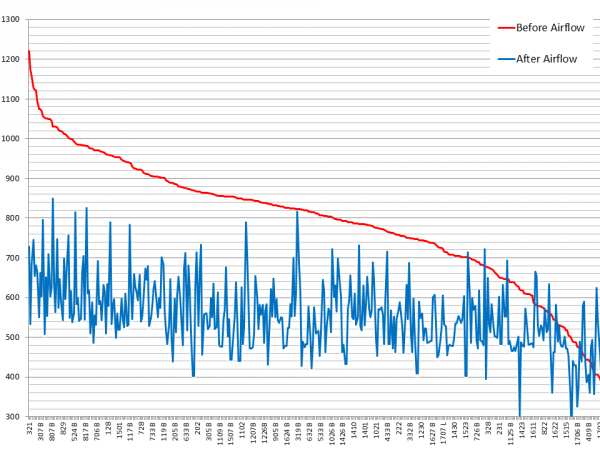
Living Room Airflow – high setting
The graph below is sorted from high to low before service.
The red line in the graph depicts airflow before the coil rejuvenation and EC motor retrofit. On the left side it begins at 1146 CFM. 20 units were above 1000 CFM on high setting. This is 67+% above the manufacturer’s design specification. When the airflow crosses the coil too quickly it does not have time to either cool or heat and dehumidify.
The red line’s slope down to the right demonstrates that the units’ CFM before service ranged from 1146 CFM to 497 CFM. 96% of the living room fan coil units were not operating as designed with airflow outside of the manufacturer’s specification curve: 540 – 660 CFM on high fan setting. 24% of the living room guestroom fan coil unit’s airflow was 50% above manufacturer’s design specifications: 900 CFM on high setting.
The blue line demonstrates that after service 88% of the unit’s airflow is within 10% of the target airflow – 600 CFM on high setting.
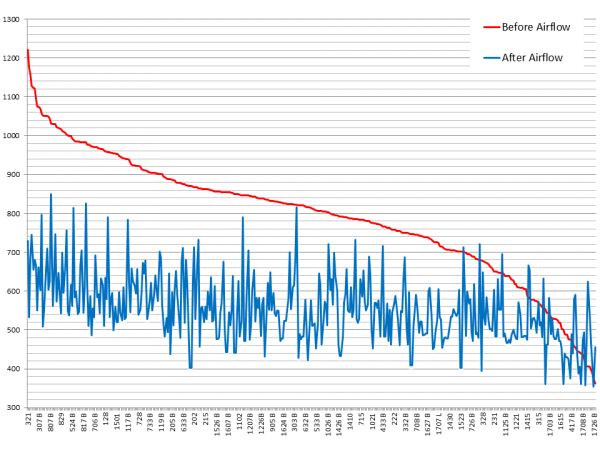
Bedroom and Studio Unit Airflow
The graph below is sorted from high to low before EC motor retrofit.
The red line in the graph depicts airflow before the coil rejuvenation and EC motor retrofit. On the left side it begins at 1221 CFM. 66 units were 50% above the manufacturer’s specification on high setting. The red line’s slope down to the right demonstrates that the unit’s CFM before service ranged from 1221 CFM to 295 CFM.
The blue line demonstrates that after service 81% of the unit’s high fan airflow is within 10% of the target airflow of 550 CFM on high setting.
The high velocity of airflow combined with loose parts and components and degrading fiber glass insulation resulted in an average sound level of 58 decibels.
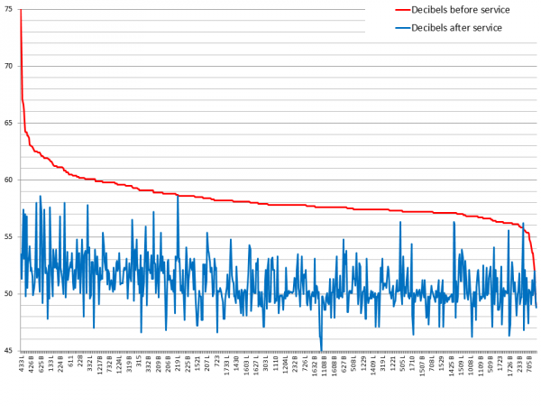
Sound decibels before and after AirRevive service
The graph below is sorted by sound decibels from high to low. The red line from high to low represents sound decibels before service. Decibels were recorded directly in front of the supply vent. 15% of the units recorded 60+ decibels which is above the sound of a typical fan coil unit.
The blue line represents sound decibels after services. The fan coil units’ sound decibels ranged from 58 to 44 decibels, averaging 51 decibels, which is almost silent from the distance of the bed.
Decibels dropped from an average of 13% or 7.2 decibels from 58.2 to 51 decibels.
AirRevive successfully completed the refurbishment by rejuvenating the coils and restoring the cabinet.
Coil temperature dropped allowing the perfect environment for the EC motor retrofit. The coils are working uniformly to achieve maximum efficiency from the EC motor.
The EC motor retrofit enhanced the units’ operation to better than new. The re-commissioned fan coil units:
Guest satisfaction improved by:
The combination of cabinet refurbishment, coil rejuvenation, insulation replacement and the EC motor retrofit resulted in units being brought back to manufacturer’s specification and operating better than new.